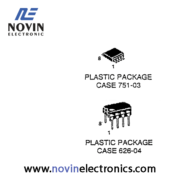
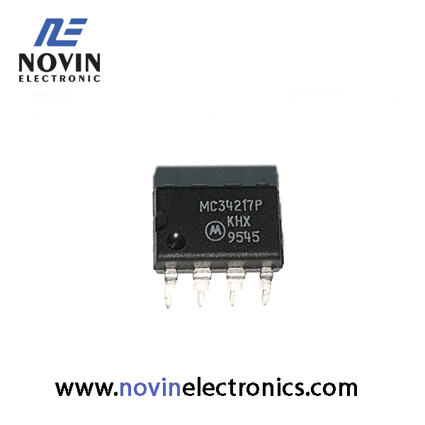
MC34217P
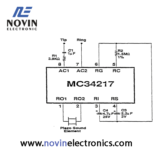
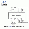
- •Pin 1 R01 ،Pin 2 R02
The tone ringer output terminals through which the sound element is driven.
•Pin 3 RI
The positive supply terminal for the oscillator , frequency divider and output buffer circi
•Pin 4 RS
The input of the threshold comparator to which diode bridge current is mirrored and sensed through an internal resistor. Nominal threshold is 1.2 volts. This pin internally clamps at 1.5 volts.
•Pin 5 RC
The oscillator terminal for the external resistor which controls the tone ringer frecuenc (R2).
•Pin 6 RG
The negative terminal of the diode bridge and the negative supply terminal of the tone generating circuit.
•Pin 7 AC2 , Pin 8 AC1
The input terminals to the full-wave diode bridge. The AC ringing signal from the telephone line energizes the ringer through this bridge.
جهت دانلود دیتاشیتMC34217P بر روی PDF زیر کلیک کنید.


فروشگاه
درباره ما
تماس با ما


دیدگاهها
هیچ دیدگاهی برای این محصول نوشته نشده است.